Product Description
Spiral bevel gearbox With Professional Technical Support
Product Description
Technical data:
1. Power: 0.37-200 (KW)
2. Output Speed: 11-226RMP,
3. Torque: 400-56000 (N. M)
4. Transmission stage: Three stage
Applications:
The products are widely applied in electricity, coal, cement, metallurgy, harbor, agriculture, shipping, lifting, environment protection, stage, logistic, weaving, paper making, light industry, plastics and other regions
1. We accept sample order.
2. We undertake the problems due to quality.
3. We supply detail answers about technical questions.
4. We are the manufacturer so we could supply the products as soon as possible.
5. At the instance of our dear customer, we can do the customized gear boxes for clients.
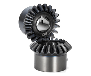
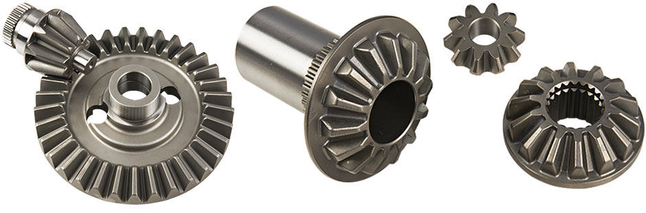
Detailed Photos
Commercial information:
1. MOQ: 1 set
2. Packing method: Polywood
3. Delivery lead time: 10-25 days
4. Price terms: FOB, CIF, EXW
5. Payment method: T/T, 30% in advance, 70% balance before delivery
6. Shipping port: HangZhou
7. OEM: We accept customized products as per your special requirement.
8. Xihu (West Lake) Dis.lines for the Selection: Usually we can select 1 machine which is suitable for you with some informations from you, such as ratio/motor speed/mounting dimension/ output torque etc.
9. If the minimum order amount is in excess of $10000, there are preferential
| input power | 0.018-96kw |
| ratio | 1-3 |
| permissable torque | 11-607N.M |
| mounting type: | footmounted |
| usage: | change direction |
Product Parameters
| Models | Input Power | Ratio | Max. Torque | Weight(kg) | Output Shaft Dia.(k6) |
| T2 | 0.014KW~1.79KW | 1~2 | 11 | 2 | Φ15 |
| T4 | 0.026KW~4.94KW | 1~2 | 31 | 10 | Φ19 |
| T6 | 0.037KW~14.9KW | 1~3 | 94 | 21 | Φ25 |
| T7 | 0.042KW~22KW | 1~3 | 139 | 32 | Φ32 |
| T8 | 0.064KW~45.6KW | 1~3 | 199 | 49 | Φ40 |
| T10 | 0.11KW~65.3KW | 1~3 | 288 | 78 | Φ45 |
| T12 | 0.188KW~96KW | 1~3 | 607 | 124 | Φ50 |
| T16 | 0.40KW~163KW | 1~3 | 1073 | 188 | Φ60 |
| T20 | 0.69KW~234KW | 1~3 | 1943 | 297 | Φ72 |
| T25 | 1.4KW~335KW | 1~3 | 3677 | 488 | Φ85 |
Ratio: 1:1, 1.5:1, 2:1, 2.5:1, 3:1
Packaging & Shipping
Company Profile
After Sales Service
| Pre-sale services | 1. Select equipment model. |
| 2.Design and manufacture products according to clients’ special requirement. | |
| 3.Train technical personal for clients | |
| Services during selling | 1.Pre-check and accept products ahead of delivery. |
| 2. Help clients to draft solving plans. | |
| After-sale services | 1.Assist clients to prepare for the first construction scheme. |
| 2. Train the first-line operators. | |
| 3.Take initiative to eliminate the trouble rapidly. | |
| 4. Provide technical exchanging. |
FAQ
FAQ:
1.Q:What kinds of gearbox can you produce for us?
A:Main products of our company: UDL series speed variator,RV series worm gear reducer, ATA series shaft mounted gearbox, X,B series gear reducer,
P series planetary gearbox and R, S, K, and F series helical-tooth reducer, more
than 1 hundred models and thousands of specifications
2.Q:Can you make as per custom drawing?
A: Yes, we offer customized service for customers.
3.Q:What is your terms of payment ?
A: 30% Advance payment by T/T after signing the contract.70% before delivery
4.Q:What is your MOQ?
A: 1 Set
Welcome to contact us for more detail information and inquiry.
If you have specific parameters and requirement for our gearbox, customization is available.
| Application: | Machinery, Industry |
|---|---|
| Function: | Change Drive Direction, Speed Reduction |
| Layout: | Right Angle |
| Hardness: | Hardened |
| Installation: | Vertical Type |
| Step: | Single-Step |
| Samples: |
US$ 1/Piece
1 Piece(Min.Order) | |
|---|
| Customization: |
Available
| Customized Request |
|---|
What are the factors to consider when selecting miter gears for an application?
When selecting miter gears for an application, several factors need to be taken into consideration to ensure optimal performance and compatibility. Here are some key factors to consider:
1. Load Requirements:
Determine the magnitude and type of load that the miter gears will be subjected to. Consider factors such as torque, speed, and direction of rotation. This information helps in selecting miter gears with the appropriate load capacity and tooth strength to handle the application’s requirements.
2. Gear Ratio:
Identify the desired gear ratio, which is the ratio of the number of teeth between the input and output gears. The gear ratio determines the speed and torque relationship between the gears. Select miter gears with a gear ratio that meets the specific speed and torque requirements of the application.
3. Accuracy and Precision:
Determine the required level of accuracy and precision for the application. Certain applications, such as precision instruments or robotics, may require miter gears with high precision and low backlash to ensure accurate motion transmission.
4. Space Constraints:
Evaluate the available space for the miter gears within the system. Consider the gear dimensions, shaft orientations, and clearance requirements. Choose miter gears that can fit within the available space while still allowing for proper meshing and alignment.
5. Noise and Vibration:
Consider the acceptable levels of noise and vibration for the application. Spiral bevel gears, for example, are known to reduce noise and vibration compared to straight bevel gears. Select miter gears with suitable tooth profiles and designs to minimize noise and vibration if required.
6. Lubrication and Maintenance:
Assess the lubrication and maintenance requirements of the miter gears. Some miter gears may require specific lubrication methods or periodic maintenance. Consider the ease of access for lubrication and maintenance tasks when selecting miter gears.
7. Environmental Factors:
Take into account the environmental conditions in which the miter gears will operate. Factors such as temperature extremes, moisture, dust, chemicals, or exposure to corrosive substances can impact gear performance. Choose miter gears that are suitable for the specific environmental conditions of the application.
8. Cost and Availability:
Consider the cost and availability of the miter gears. Evaluate the overall value proposition, including the initial cost, long-term maintenance costs, and the availability of spare parts. Balance the cost factor with the desired performance and reliability.
By considering these factors, engineers and designers can select miter gears that are well-suited for the application’s requirements, ensuring efficient and reliable operation.
“`
How do miter gears contribute to space-saving in mechanical systems?
Miter gears are known for their ability to contribute to space-saving in mechanical systems. Here’s an explanation of how they achieve this:
1. Right Angle Transmission:
Miter gears are specifically designed to transmit rotational motion at a 90-degree angle. This allows the input and output shafts to be positioned perpendicular to each other, enabling compact and space-efficient mechanical arrangements. By utilizing miter gears, complex mechanical systems can be designed with a smaller footprint.
2. Compact Gearbox Design:
Miter gears can be used in gearbox assemblies where space is a constraint. Their right angle transmission capability eliminates the need for additional components, such as bevel gearboxes or universal joints, that would otherwise be required to change the direction of the rotational motion. This compact design helps save space and simplifies the overall mechanical system.
3. Shaft Intersections and Crossings:
Miter gears allow for shaft intersections and crossings without interfering with each other. By using miter gears, designers can arrange shafts to intersect or cross paths at right angles, minimizing the space required for shaft routing. This is particularly advantageous in applications where multiple shafts need to be accommodated within a limited space envelope.
4. Versatility in Spatial Orientation:
Miter gears provide flexibility in spatial orientation, allowing for various mounting configurations. They can be used in vertical, horizontal, or angled positions, depending on the system requirements. This versatility enables designers to optimize space utilization and adapt to different mechanical layouts.
5. Integration in Compact Machinery:
Miter gears are commonly employed in compact machinery and equipment where space-saving is crucial. Examples include robotics, precision instruments, medical devices, aerospace systems, and automotive applications. By utilizing miter gears, designers can achieve compact and efficient mechanical designs without compromising performance.
6. Elimination of Space-Intensive Components:
By using miter gears, certain space-intensive components, such as drive belts, pulleys, or chain drives, can be eliminated from the system. Miter gears provide a direct and efficient power transmission mechanism, reducing the need for additional space-consuming elements, thus contributing to overall space savings.
In summary, miter gears contribute to space-saving in mechanical systems by providing right angle transmission, enabling compact gearbox designs, facilitating shaft intersections and crossings, offering versatility in spatial orientation, integrating well in compact machinery, and eliminating space-intensive components. These factors make miter gears a valuable choice for applications where optimizing space utilization is paramount.
What are miter gears and how are they used?
Miter gears are a type of bevel gears that have equal numbers of teeth and are used to transmit motion and power between intersecting shafts. Here’s a detailed explanation:
1. Gear Design:
Miter gears have a conical shape with teeth cut at an angle of 90 degrees to the gear’s face. The teeth are cut in a straight manner, similar to spur gears, but instead of being parallel to the gear’s axis, they are cut at a right angle to transmit motion between intersecting shafts.
2. Intersecting Shafts:
Miter gears are primarily used to transmit power and motion between two shafts that intersect at a 90-degree angle. The gear’s conical shape allows the teeth to mesh correctly when the shafts are perpendicular to each other.
3. Change of Shaft Direction:
Miter gears are commonly used to change the direction of rotation between intersecting shafts. By meshing the teeth of two miter gears, the input shaft’s rotational motion can be transferred to the output shaft at a 90-degree angle, effectively changing the direction of rotation.
4. Speed Reduction or Increase:
Depending on the arrangement of the miter gears, they can be used to achieve speed reduction or speed increase. By using different numbers of teeth on the miter gears or combining them with other gears, such as spur gears, the rotational speed can be adjusted to match the desired output speed.
5. Compact Design:
Miter gears are known for their compact design, making them suitable for applications where space is limited. The intersecting shafts and the conical shape of the gears allow for efficient power transmission while occupying a small footprint.
6. Applications:
Miter gears find applications in various industries and devices, including:
- Power transmission systems
- Automotive differentials
- Mechanical clocks
- Robotics
- Printing machinery
- Woodworking tools
- Camera lenses
In summary, miter gears are bevel gears with equal numbers of teeth that are used to transmit motion and power between intersecting shafts at a 90-degree angle. They are commonly employed to change the direction of rotation, achieve speed reduction or increase, and maintain a compact design in various mechanical systems.


editor by CX 2023-10-12