Product Description
T series high precision reductor spiral bevel gearbox for packing machine
Product Description
Technical data:
1. Power: 0.37-200 (KW)
2. Output Speed: 11-226RMP,
3. Torque: 400-56000 (N. M)
4. Transmission stage: Three stage
Applications:
The products are widely applied in electricity, coal, cement, metallurgy, harbor, agriculture, shipping, lifting, environment protection, stage, logistic, weaving, paper making, light industry, plastics and other regions
1. We accept sample order.
2. We undertake the problems due to quality.
3. We supply detail answers about technical questions.
4. We are the manufacturer so we could supply the products as soon as possible.
5. At the instance of our dear customer, we can do the customized gear boxes for clients.
Detailed Photos
Commercial information:
1. MOQ: 1 set
2. Packing method: Polywood
3. Delivery lead time: 10-25 days
4. Price terms: FOB, CIF, EXW
5. Payment method: T/T, 30% in advance, 70% balance before delivery
6. Shipping port: HangZhou
7. OEM: We accept customized products as per your special requirement.
8. Xihu (West Lake) Dis.lines for the Selection: Usually we can select 1 machine which is suitable for you with some informations from you, such as ratio/motor speed/mounting dimension/ output torque etc.
9. If the minimum order amount is in excess of $10000, there are preferential
| input power | 0.018-96kw |
| ratio | 1-3 |
| permissable torque | 11-607N.M |
| mounting type: | footmounted |
| usage: | change direction |
Product Parameters
| Models | Input Power | Ratio | Max. Torque | Weight(kg) | Output Shaft Dia.(k6) |
| T2 | 0.014KW~1.79KW | 1~2 | 11 | 2 | Φ15 |
| T4 | 0.026KW~4.94KW | 1~2 | 31 | 10 | Φ19 |
| T6 | 0.037KW~14.9KW | 1~3 | 94 | 21 | Φ25 |
| T7 | 0.042KW~22KW | 1~3 | 139 | 32 | Φ32 |
| T8 | 0.064KW~45.6KW | 1~3 | 199 | 49 | Φ40 |
| T10 | 0.11KW~65.3KW | 1~3 | 288 | 78 | Φ45 |
| T12 | 0.188KW~96KW | 1~3 | 607 | 124 | Φ50 |
| T16 | 0.40KW~163KW | 1~3 | 1073 | 188 | Φ60 |
| T20 | 0.69KW~234KW | 1~3 | 1943 | 297 | Φ72 |
| T25 | 1.4KW~335KW | 1~3 | 3677 | 488 | Φ85 |
Ratio: 1:1, 1.5:1, 2:1, 2.5:1, 3:1
Packaging & Shipping
Company Profile
After Sales Service
| Pre-sale services | 1. Select equipment model. |
| 2.Design and manufacture products according to clients’ special requirement. | |
| 3.Train technical personal for clients | |
| Services during selling | 1.Pre-check and accept products ahead of delivery. |
| 2. Help clients to draft solving plans. | |
| After-sale services | 1.Assist clients to prepare for the first construction scheme. |
| 2. Train the first-line operators. | |
| 3.Take initiative to eliminate the trouble rapidly. | |
| 4. Provide technical exchanging. |
FAQ
FAQ:
1.Q:What kinds of gearbox can you produce for us?
A:Main products of our company: UDL series speed variator,RV series worm gear reducer, ATA series shaft mounted gearbox, X,B series gear reducer,
P series planetary gearbox and R, S, K, and F series helical-tooth reducer, more
than 1 hundred models and thousands of specifications
2.Q:Can you make as per custom drawing?
A: Yes, we offer customized service for customers.
3.Q:What is your terms of payment ?
A: 30% Advance payment by T/T after signing the contract.70% before delivery
4.Q:What is your MOQ?
A: 1 Set
Welcome to contact us for more detail information and inquiry.
If you have specific parameters and requirement for our gearbox, customization is available.
| Application: | Machinery, Industry |
|---|---|
| Function: | Change Drive Direction, Speed Reduction |
| Layout: | Right Angle |
| Hardness: | Hardened |
| Installation: | Vertical Type |
| Step: | Single-Step |
| Samples: |
US$ 1/Piece
1 Piece(Min.Order) | |
|---|
| Customization: |
Available
| Customized Request |
|---|
How do miter gears handle changes in direction and torque transmission?
Miter gears are specifically designed to handle changes in direction and torque transmission efficiently. Here’s an explanation of how they accomplish this:
1. Right Angle Transmission:
Miter gears are primarily used to transmit rotational motion at a 90-degree angle. When two miter gears with intersecting shafts are meshed together, they allow the input and output shafts to be positioned perpendicular to each other. This right angle transmission capability enables changes in direction within a compact space.
2. Interlocking Tooth Design:
Miter gears have teeth that are cut at a specific angle to match the gear’s cone shape. When two miter gears mesh, their teeth interlock and transfer torque between the gears. The interlocking tooth design ensures a smooth and efficient torque transmission, minimizing power loss and maximizing mechanical efficiency.
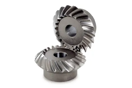
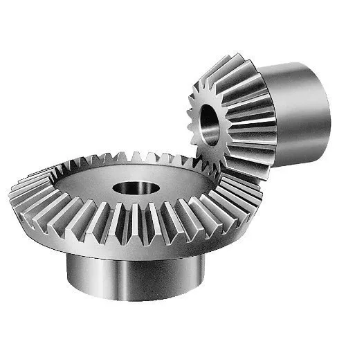
3. Bevel Gear Configuration:
Miter gears belong to the bevel gear family, which includes straight bevel gears and spiral bevel gears. Straight bevel gears have straight-cut teeth and are suitable for applications with moderate torque and speed requirements. Spiral bevel gears have curved teeth that gradually engage, providing higher torque capacity and smoother operation. The choice between straight and spiral bevel gears depends on the specific application’s torque and performance requirements.
4. Meshing Alignment:
Proper alignment of miter gears is crucial for efficient torque transmission and smooth operation. The gears must be precisely positioned and aligned to ensure accurate meshing of the teeth. This alignment is typically achieved using precision machining and assembly techniques to maintain the desired gear contact pattern and tooth engagement.
5. Load Distribution:
When torque is transmitted through miter gears, the load is distributed across multiple teeth rather than concentrated on a single tooth. This load distribution helps to minimize tooth wear, reduce stress concentrations, and increase the overall load-carrying capacity of the gears.
6. Lubrication:
Proper lubrication is essential for the smooth operation and longevity of miter gears. Lubricants reduce friction and wear between the gear teeth, ensuring efficient torque transmission and minimizing heat generation. The type and method of lubrication depend on the specific application and operating conditions.
7. Backlash Control:
Backlash refers to the slight clearance between the mating teeth of gears. Miter gears can be designed with specific tooth profiles and manufacturing techniques to control backlash and minimize any unwanted movement or play. This helps maintain accuracy and precision in direction and torque transmission.
In summary, miter gears handle changes in direction and torque transmission through their right angle transmission capability, interlocking tooth design, bevel gear configuration, precise meshing alignment, load distribution across teeth, proper lubrication, and backlash control. These features make miter gears an effective choice for applications that require efficient and reliable direction and torque transmission.
Can you provide examples of machinery that utilize miter gears?
Miter gears find application in various machinery and mechanical systems. Here are some examples of machinery that utilize miter gears:
1. Power Tools:
Miter saws and compound miter saws commonly use miter gears to transmit power at a 90-degree angle, allowing for precise cutting angles and bevels.
2. Robotics:
Miter gears are frequently used in robotic systems to transmit motion between joints and enable accurate movement and positioning.
3. Automotive Systems:
Miter gears are employed in automotive applications such as differentials, steering systems, and transfer cases to transmit power and change drive direction.
4. Printing Machinery:
Miter gears are utilized in printing presses to transfer power and change the orientation of rotating cylinders, enabling proper paper feeding and print registration.
5. Aerospace Systems:
Miter gears are found in aerospace applications like aircraft landing gear systems, where they are used to transmit power and change the direction of motion.
6. Medical Devices:
Medical equipment, such as surgical robots and imaging devices, may incorporate miter gears to achieve compact designs and precise motion transmission.
7. Industrial Machinery:
Miter gears are used in various industrial machinery, including conveyors, packaging equipment, and assembly line systems, to change the direction of motion and transmit power efficiently.
8. Construction Equipment:
Construction machinery, such as excavators and cranes, may employ miter gears in their rotating mechanisms to transmit power and change the direction of motion.
9. Marine Systems:
Miter gears are utilized in marine applications like propulsion systems and steering mechanisms to transmit power and change the direction of rotation.
10. HVAC Systems:
Heating, ventilation, and air conditioning (HVAC) systems may incorporate miter gears in their fan assemblies to change the direction of rotation and transmit power efficiently.
These are just a few examples of machinery that utilize miter gears. The versatility and space-saving characteristics of miter gears make them suitable for a wide range of applications across various industries.
Can you explain the unique design of miter gear teeth?
The design of miter gear teeth is distinct and plays a crucial role in the functionality of these gears. Here’s a detailed explanation:
1. Tooth Shape:
Miter gear teeth have a straight shape, similar to spur gears. However, unlike spur gears where the teeth are parallel to the gear axis, miter gear teeth are cut at a right angle to the gear’s face. This allows the teeth to engage correctly when two miter gears mesh together at a 90-degree angle.
2. Equal Number of Teeth:
Miter gears have an equal number of teeth on both gears in a pair. This ensures proper meshing and smooth transmission of rotational motion between the gears. The equal number of teeth is essential for maintaining a constant speed ratio and preventing any slippage or irregular motion.
3. Conical Shape:
Another unique aspect of miter gear teeth is the conical shape of the gears themselves. The teeth are cut on the conical surface, which allows for proper engagement and transmission of motion between intersecting shafts. The conical shape ensures that the teeth mesh correctly, providing efficient power transmission at the desired angle.
4. Meshing at 90-Degree Angle:
Miter gears are designed to mesh at a 90-degree angle, allowing for power transmission between intersecting shafts. The teeth are specifically cut to facilitate this arrangement, ensuring that the gears engage smoothly and transmit rotational motion without any loss or disruption.
5. Tooth Contact and Load Distribution:
When miter gears mesh, the contact between the teeth occurs along a single line, known as the line of contact. This concentrated contact area enables effective load distribution and ensures that the gear teeth bear the transmitted torque evenly. Proper tooth contact is vital for minimizing wear and maintaining the longevity of the gears.
6. Lubrication and Noise Reduction:
The unique design of miter gear teeth can influence lubrication and noise levels. Adequate lubrication is essential to reduce friction and wear between the teeth during operation. Additionally, the straight tooth profile of miter gears tends to produce more noise compared to gears with helical or curved teeth. Proper lubrication and noise reduction measures are often employed to optimize the performance of miter gears.
In summary, the unique design of miter gear teeth includes their straight shape, equal number of teeth, conical shape of the gears, meshing at a 90-degree angle, tooth contact along a line, and considerations for lubrication and noise reduction. These design features ensure efficient power transmission, proper load distribution, and reliable operation in mechanical systems that utilize miter gears.


editor by CX 2023-10-11