Product Description
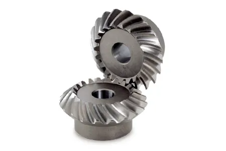
Bevel Miter Pinion Gear And Shaft
1.; Material:; Carbon steel such as 20CrMnTi
2.; Hardness:; HRC58-62
3.; OEM offered
We manufacture:;bevel miter gear,;spiral bevel gear,; electric tool gear,; electric tool pinion,; electronic tool gear,; electronic tool pinion
1.; Material:; 20CrMnTi
2.; Processing:; Forged,; machined,; heat treatment
3.; Quality:; OEM.;
4.; Can design and manufacture as per your drawing or sample
A Professional on Drawing analysis,; Meeting discussing,; program auditing,; PC & QC.;
We can make all kinds of gears according to clients drawing and specifications,; specializing in non-standard items.;
At present,; we have all kinds of CNC machines as well as common used machines to meet different processing requirements.;
So,; please send us your inquires with detailed drawings,; specifications,; quality required,; and actual samples if available
We pay most attention on quality and our QC will inspect the goods for you before delivery.; You will get our report.;
|
| Manufacturing Method: | Cut Gear |
|---|---|
| Toothed Portion Shape: | Bevel Wheel |
| Material: | Alloy |
| Customization: |
Available
| Customized Request |
|---|
.shipping-cost-tm .tm-status-off{background: none;padding:0;color: #1470cc}
| Shipping Cost:
Estimated freight per unit. |
about shipping cost and estimated delivery time. |
|---|
| Payment Method: |
|
|---|---|
|
Initial Payment Full Payment |
| Currency: | US$ |
|---|
| Return&refunds: | You can apply for a refund up to 30 days after receipt of the products. |
|---|
How do miter gears handle changes in direction and torque transmission?
Miter gears are specifically designed to handle changes in direction and torque transmission efficiently. Here’s an explanation of how they accomplish this:
1. Right Angle Transmission:
Miter gears are primarily used to transmit rotational motion at a 90-degree angle. When two miter gears with intersecting shafts are meshed together, they allow the input and output shafts to be positioned perpendicular to each other. This right angle transmission capability enables changes in direction within a compact space.
2. Interlocking Tooth Design:
Miter gears have teeth that are cut at a specific angle to match the gear’s cone shape. When two miter gears mesh, their teeth interlock and transfer torque between the gears. The interlocking tooth design ensures a smooth and efficient torque transmission, minimizing power loss and maximizing mechanical efficiency.
3. Bevel Gear Configuration:
Miter gears belong to the bevel gear family, which includes straight bevel gears and spiral bevel gears. Straight bevel gears have straight-cut teeth and are suitable for applications with moderate torque and speed requirements. Spiral bevel gears have curved teeth that gradually engage, providing higher torque capacity and smoother operation. The choice between straight and spiral bevel gears depends on the specific application’s torque and performance requirements.
4. Meshing Alignment:
Proper alignment of miter gears is crucial for efficient torque transmission and smooth operation. The gears must be precisely positioned and aligned to ensure accurate meshing of the teeth. This alignment is typically achieved using precision machining and assembly techniques to maintain the desired gear contact pattern and tooth engagement.
5. Load Distribution:
When torque is transmitted through miter gears, the load is distributed across multiple teeth rather than concentrated on a single tooth. This load distribution helps to minimize tooth wear, reduce stress concentrations, and increase the overall load-carrying capacity of the gears.
6. Lubrication:
Proper lubrication is essential for the smooth operation and longevity of miter gears. Lubricants reduce friction and wear between the gear teeth, ensuring efficient torque transmission and minimizing heat generation. The type and method of lubrication depend on the specific application and operating conditions.
7. Backlash Control:
Backlash refers to the slight clearance between the mating teeth of gears. Miter gears can be designed with specific tooth profiles and manufacturing techniques to control backlash and minimize any unwanted movement or play. This helps maintain accuracy and precision in direction and torque transmission.
In summary, miter gears handle changes in direction and torque transmission through their right angle transmission capability, interlocking tooth design, bevel gear configuration, precise meshing alignment, load distribution across teeth, proper lubrication, and backlash control. These features make miter gears an effective choice for applications that require efficient and reliable direction and torque transmission.

How do you calculate the gear ratio in a miter gear assembly?
The gear ratio in a miter gear assembly can be calculated by considering the number of teeth on the gears involved. Here’s a step-by-step explanation:
1. Determine the Number of Teeth:
Identify the number of teeth on both the driving gear (input gear) and the driven gear (output gear) in the miter gear assembly. The number of teeth can usually be found in the gear specifications or by physically counting the teeth.
2. Calculate the Gear Ratio:
To calculate the gear ratio, divide the number of teeth on the driven gear (output gear) by the number of teeth on the driving gear (input gear). The formula for calculating the gear ratio is:
Gear Ratio = Number of Teeth on Driven Gear / Number of Teeth on Driving Gear
3. Simplify the Ratio (Optional):
If the resulting gear ratio is a fraction, it can be simplified to its simplest form. Divide both the numerator and the denominator by their greatest common divisor to simplify the ratio.
4. Interpret the Gear Ratio:
The gear ratio indicates the relationship between the rotational speed or angular velocity of the driving gear and the driven gear. It represents how many times the driven gear rotates for each rotation of the driving gear. For example, a gear ratio of 2:1 means that the driven gear rotates twice for every rotation of the driving gear.
5. Consider the Significance:
The gear ratio has practical implications in determining the mechanical advantage and speed reduction/amplification in a miter gear assembly. A gear ratio greater than 1 indicates a speed reduction and increased torque, while a gear ratio less than 1 indicates a speed amplification and decreased torque.
In summary, the gear ratio in a miter gear assembly is calculated by dividing the number of teeth on the driven gear by the number of teeth on the driving gear. This ratio represents the relationship between the rotational speeds of the gears and provides insights into the mechanical advantage and speed transformation in the gear assembly.
How do miter gears differ from other types of gears?
Miter gears possess distinct characteristics that set them apart from other types of gears. Here’s a detailed explanation:
1. Shape and Tooth Orientation:
Miter gears have a conical shape with teeth cut at a 90-degree angle to the gear’s face. This differs from other gears, such as spur gears or helical gears, which have cylindrical or helical tooth profiles. The conical shape of miter gears allows them to transmit motion between intersecting shafts at a right angle.
2. Shaft Arrangement:
Miter gears are specifically designed for transmitting power and motion between intersecting shafts. They are suitable for applications where the shafts intersect at a 90-degree angle. In contrast, other types of gears, such as spur gears or worm gears, are typically used for parallel or non-intersecting shafts.
3. Direction of Rotation:
One of the primary differences lies in the capability of miter gears to change the direction of rotation. By meshing two miter gears, the input rotational motion can be redirected at a 90-degree angle. This is in contrast to other gears that primarily transmit motion in the same direction as the input.
4. Speed Reduction or Increase:
Miter gears can be used to achieve speed reduction or increase by varying the number of teeth on the gears or combining them with other gears. This allows for adjusting the rotational speed to match the desired output speed. In contrast, other gears may have different mechanisms, such as helical gears with inclined teeth for smooth and quiet operation or worm gears for high speed reduction.
5. Compact Design:
Miter gears are known for their compact design. The intersecting shafts and the conical shape of the gears enable efficient power transmission while occupying minimal space. This compactness is particularly advantageous in applications where size and weight constraints are critical factors.
6. Application-Specific Use:
Miter gears find specific applications where the requirement is to change the direction of rotation between intersecting shafts at a 90-degree angle. They are commonly used in power transmission systems, automotive differentials, mechanical clocks, robotics, printing machinery, woodworking tools, camera lenses, and other devices.
In summary, miter gears differ from other types of gears in terms of their conical shape, suitability for intersecting shafts at a 90-degree angle, ability to change the direction of rotation, capability for speed reduction or increase, compact design, and application-specific use. These unique characteristics make miter gears valuable in various mechanical systems where specific motion transmission requirements need to be met.


editor by CX 2023-12-13