Product Description
tractor miter spiral plastic right internal CHINAMFG pinion Hypoid Harmonic Cage Cycloidal Magnetic Differential helical spur bevel gear
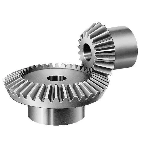
Application of spur bevel gear
Sure, here are some of the applications of spur bevel gears:
- Differentials: Spur bevel gears are used in differentials to transmit power from the driveshaft to the wheels.
- Wind turbines: Spur bevel gears are used in wind turbines to transmit power from the blades to the generator.
- Robotics: Spur bevel gears are used in robotics to move the robot’s arms and joints.
- Machine tools: Spur bevel gears are used in machine tools, such as lathes and milling machines, to transmit power from the motor to the cutting tool.
- Conveyors: Spur bevel gears are used in conveyors to transmit power from the motor to the conveyor belt.
- Mixers: Spur bevel gears are used in mixers to transmit power from the motor to the mixing bowl.
Spur bevel gears are a versatile type of gear that can be used in a wide variety of applications. They are characterized by their high efficiency, smooth operation, and low noise. Spur bevel gears are also relatively compact and lightweight, making them a good choice for applications where space is limited.
Here are some of the advantages of using spur bevel gears:
- High efficiency: Spur bevel gears are more efficient than other types of gears, such as helical gears. This is because the teeth of spur bevel gears mesh together more smoothly, which reduces friction and wear.
- Smooth operation: Spur bevel gears operate more smoothly than other types of gears. This is because the teeth of spur bevel gears mesh together more gradually, which reduces shock and vibration.
- Low noise: Spur bevel gears operate more quietly than other types of gears. This is because the teeth of spur bevel gears mesh together more smoothly, which reduces friction and wear.
- Compact size: Spur bevel gears are typically smaller and lighter than other types of gears. This is because spur bevel gears can be designed with more compact tooth profiles.
- Wide range of applications: Spur bevel gears can be used in a wide range of applications. This is because they are available in a wide range of sizes and configurations.
Overall, spur bevel gears are a versatile and efficient type of gear that can be used in a wide variety of applications. They are characterized by their high efficiency, smooth operation, low noise, compact size, and wide range of applications.
| Application: | Motor, Electric Cars, Motorcycle, Machinery, Marine, Toy, Agricultural Machinery, Car |
|---|---|
| Hardness: | Hardened Tooth Surface |
| Gear Position: | Internal Gear |
| Manufacturing Method: | Cast Gear |
| Toothed Portion Shape: | Spur Gear |
| Material: | Stainless Steel |
| Samples: |
US$ 9999/Piece
1 Piece(Min.Order) | |
|---|
What is the impact of tooth profile on the efficiency of miter gears?
The tooth profile of miter gears plays a crucial role in determining their efficiency. Miter gears are a type of bevel gears that transmit rotational motion between intersecting shafts. The tooth profile refers to the shape and design of the teeth on the gear.
The efficiency of miter gears is influenced by several factors related to the tooth profile:
- Tooth Shape: The shape of the teeth can significantly affect the efficiency. Ideally, the tooth profile should have a smooth and gradual transition from one tooth to the next. This ensures a uniform distribution of load and minimizes the impact of meshing forces, resulting in higher efficiency.
- Tooth Size: The size of the teeth, including their length and width, can impact the efficiency of miter gears. Larger teeth generally provide better load-carrying capacity and reduce the risk of tooth failure. However, excessively large teeth can increase friction and reduce efficiency.
- Tooth Helix Angle: The helix angle of the teeth determines the spiral orientation of the gear. Miter gears with a higher helix angle tend to have smoother meshing action and lower noise levels. This can contribute to improved efficiency by reducing friction and minimizing energy losses.
- Tooth Contact Pattern: The contact pattern between the teeth of miter gears should be optimized for efficient power transmission. Proper tooth contact ensures uniform load distribution and minimizes localized wear. A well-designed tooth profile creates a desirable contact pattern, resulting in higher efficiency.
Therefore, when designing or selecting miter gears, careful consideration should be given to the tooth profile. Optimal tooth shape, size, helix angle, and contact pattern can significantly enhance the efficiency of miter gears, leading to improved overall performance and reduced energy losses.

How do you calculate the gear ratio in a miter gear assembly?
The gear ratio in a miter gear assembly can be calculated by considering the number of teeth on the gears involved. Here’s a step-by-step explanation:
1. Determine the Number of Teeth:
Identify the number of teeth on both the driving gear (input gear) and the driven gear (output gear) in the miter gear assembly. The number of teeth can usually be found in the gear specifications or by physically counting the teeth.
2. Calculate the Gear Ratio:
To calculate the gear ratio, divide the number of teeth on the driven gear (output gear) by the number of teeth on the driving gear (input gear). The formula for calculating the gear ratio is:
Gear Ratio = Number of Teeth on Driven Gear / Number of Teeth on Driving Gear
3. Simplify the Ratio (Optional):
If the resulting gear ratio is a fraction, it can be simplified to its simplest form. Divide both the numerator and the denominator by their greatest common divisor to simplify the ratio.
4. Interpret the Gear Ratio:
The gear ratio indicates the relationship between the rotational speed or angular velocity of the driving gear and the driven gear. It represents how many times the driven gear rotates for each rotation of the driving gear. For example, a gear ratio of 2:1 means that the driven gear rotates twice for every rotation of the driving gear.
5. Consider the Significance:
The gear ratio has practical implications in determining the mechanical advantage and speed reduction/amplification in a miter gear assembly. A gear ratio greater than 1 indicates a speed reduction and increased torque, while a gear ratio less than 1 indicates a speed amplification and decreased torque.
In summary, the gear ratio in a miter gear assembly is calculated by dividing the number of teeth on the driven gear by the number of teeth on the driving gear. This ratio represents the relationship between the rotational speeds of the gears and provides insights into the mechanical advantage and speed transformation in the gear assembly.
How do miter gears differ from other types of gears?
Miter gears possess distinct characteristics that set them apart from other types of gears. Here’s a detailed explanation:
1. Shape and Tooth Orientation:
Miter gears have a conical shape with teeth cut at a 90-degree angle to the gear’s face. This differs from other gears, such as spur gears or helical gears, which have cylindrical or helical tooth profiles. The conical shape of miter gears allows them to transmit motion between intersecting shafts at a right angle.
2. Shaft Arrangement:
Miter gears are specifically designed for transmitting power and motion between intersecting shafts. They are suitable for applications where the shafts intersect at a 90-degree angle. In contrast, other types of gears, such as spur gears or worm gears, are typically used for parallel or non-intersecting shafts.
3. Direction of Rotation:
One of the primary differences lies in the capability of miter gears to change the direction of rotation. By meshing two miter gears, the input rotational motion can be redirected at a 90-degree angle. This is in contrast to other gears that primarily transmit motion in the same direction as the input.
4. Speed Reduction or Increase:
Miter gears can be used to achieve speed reduction or increase by varying the number of teeth on the gears or combining them with other gears. This allows for adjusting the rotational speed to match the desired output speed. In contrast, other gears may have different mechanisms, such as helical gears with inclined teeth for smooth and quiet operation or worm gears for high speed reduction.
5. Compact Design:
Miter gears are known for their compact design. The intersecting shafts and the conical shape of the gears enable efficient power transmission while occupying minimal space. This compactness is particularly advantageous in applications where size and weight constraints are critical factors.
6. Application-Specific Use:
Miter gears find specific applications where the requirement is to change the direction of rotation between intersecting shafts at a 90-degree angle. They are commonly used in power transmission systems, automotive differentials, mechanical clocks, robotics, printing machinery, woodworking tools, camera lenses, and other devices.
In summary, miter gears differ from other types of gears in terms of their conical shape, suitability for intersecting shafts at a 90-degree angle, ability to change the direction of rotation, capability for speed reduction or increase, compact design, and application-specific use. These unique characteristics make miter gears valuable in various mechanical systems where specific motion transmission requirements need to be met.


editor by CX 2023-09-28